30 янв. 2025 г.

DIGITAL SIMULATION OF POWER PLANTS POWER PLANT SIMULATOR PROGRAM
Energy is life…

By now our life form can no longer exist without a kind of energy such as “Electricity”. It is electrical energy that we have been utilizing in all aspects of existence for a long time. In fact, we can convert the electrical energy into mechanical and thermal energy, acoustic and chemical energy, magnetic and optical energy. Our work system, healthcare system, defensive system, scientific system, communication system, transportation system, entertainment system and much more are all founded on the use of electricity.
But the electrical energy cannot be simply arisen by itself. It is necessary to generate it; that is what generating power plants of different types serve. Mankind has invented many ways of converting different types of energy into electrical energy - Hydroelectric Power Plants (water flow), Thermal Power Plants (fuel combustion), Nuclear Power Plants (nuclear/steam fission), Solar Power Plants (optical range), Wind Power Plants (air mass flow) ....
No matter what kind of power plant - it has to be built and the management staff has to be trained to operate the aggregates correctly.

It is with the personnel of power plants that, in recent years, losses in quality and quantity have been observed. The personnel of previous generations are gradually being reduced, retired, and new staff is in no hurry to take their places in a timely and appropriate manner. We observe a shortage of specialists at many critical levels of personnel at generating power plants.
Moreover, there is no real problem with educational institutions - there are no questions about their availability, quality and a variety of directions for future specialists, because all of this is undeniably available here and now.
Whether the problem is found in the methods of perception of a new generation - maybe... Because in today's world of high technology and digitalization, people are used to accept experience and knowledge mainly through computers, 3D graphics, real-time interactivity, to see/hear everything at once.
Inasmuch as modern tasks require modern solutions, the KNEP Institute created “Power Plant Simulator” Software, a computer program for power plants, at the end of 2024.
This software program solves the following tasks:
- Promoting the power industry to the new generation.
- Recreating any power plant as a digital model.
- Presentation of power plant facilities to working and managing personnel.
- Training of Engineers and Operators to understand the basics of working in a power plant.
- Practicing both normal and emergency modes of equipment.
- Real-time industrial imaging and designing.
SIMULATOR PROGRAM CREATION
Now, what happens if you take a group of constructors, programmers, designers and engineers and give them a task to create for each of them that they can do at this stage of their education...? Probably the programmer will do the programming code, the engineer will create a diagram of the power units and aggregates, the designer will design a layout of potential complex, and the constructor will create an assembly form for each equipment... This is the most likely scenario... Afterwards, each of them will get a credit or other reward, and then everyone will go away until next time this cycle is repeated.
But what if all of the above people came together and set out to invent a product that is needed to solve today's issues? They might agree with each other and together create something new.
This constructed a team with a common idea - to create a digital “power plant simulation unit”.
Simulation Unit is a program module written in the C+ programming language and adapted in Visual Studio 2019 and later on in Visual Studio 2022.
The Simulation Unit serves as a data center of interactions between the power nodes of aggregates and the user control.
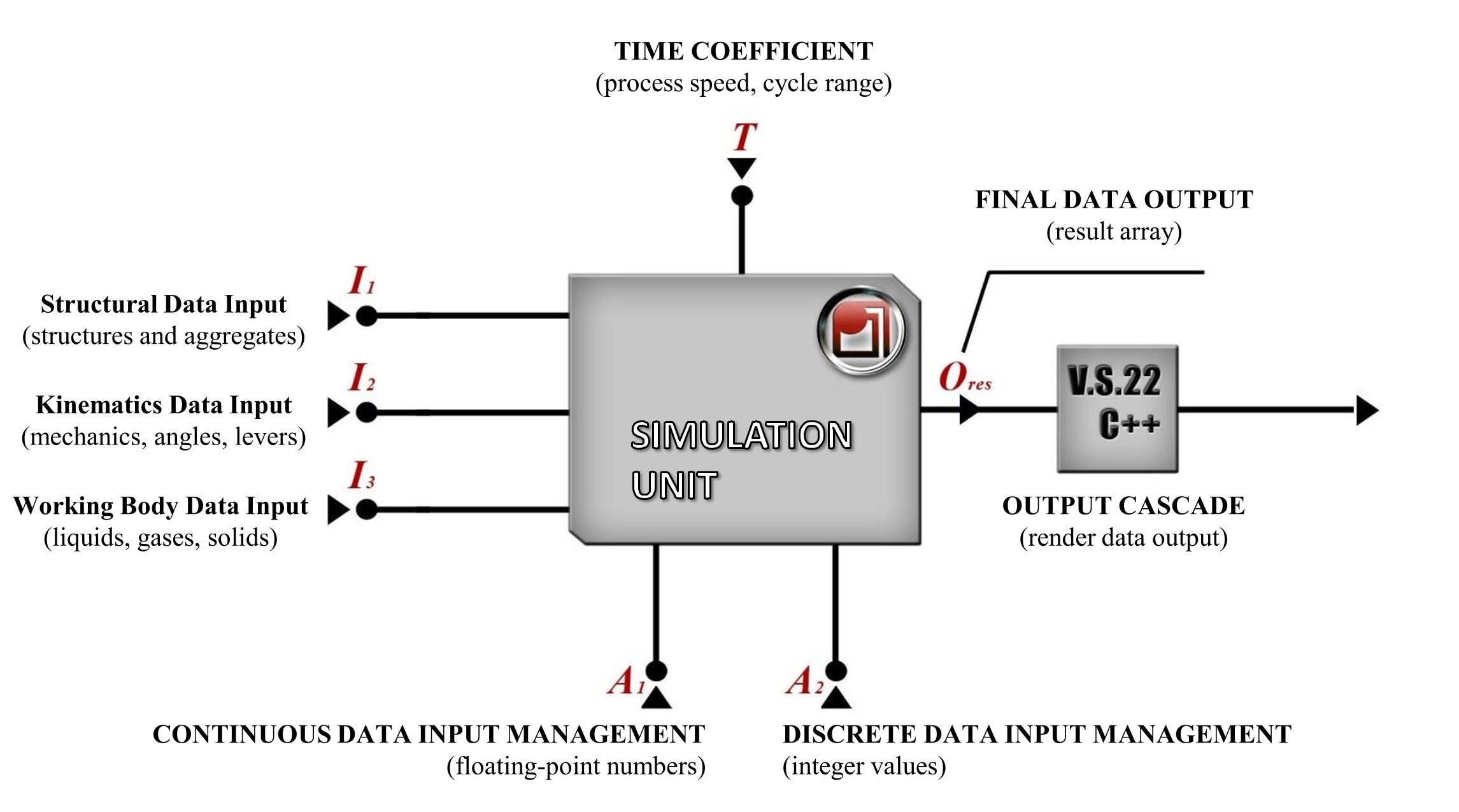
If one looks at the simplified flow scheme of the Simulation Unit, one can identify three initial data input lines: I1, I2, I3, two control lines: A1, A2, one input of time coefficient: T, and one common output Ores of calculated final data.
The I1 Structural Data Input is a channel for loading information such as models of objects, aggregates, power units and other components. The input data format for loaded objects is a proprietary undocumented FBX format.
The I2 Kinematics Data Input is a channel for loading information about mechanical connections, bearing points, angles of deflection of joints and blades, limits of motion of certain units of various systems.
The I3 Working Body Data Input is a channel for loading information about the working body of the aggregates, e.g. liquids, gases, solids. Information on temperature, pressure, viscosity, turbulence, expansion limits and phase transitions are also loaded along this data line.
The input channel for the T time coefficient data is a time multiplier and interval setting for various cycles, specified in both channel I2 and channel I3. Manipulating the numerical values in channel T, it is possible to speed up or slow down the overall process of the required facilities, to limit the range of cycle operations and to select the speed mode of calculations required by a user.
The channels of managing the input of continuous and discrete data A1 and A2 are methods of interaction of user (operator) of the program with modes of operation of simulation of digital station, power units, aggregates, control panels. These management channels are divided into the A1 continuous data input (the signal is a continuous floating-point value), that allows to simulate regulators and analog input devices, and the A2 discrete data input (the signal is an integer discrete value), that allows to simulate buttons, toggle switches, switches and stepping input devices.
The final result of computations of the Simulation Unit represents an array of coordinate streams (motions, rotations, scale changes, deformations) for different nodes of simulated systems, as well as the resulting numerical values obtained from the formulas of the aggregates.
Output of the calculation results is performed through the output channel Ores, that switches with the output stage of the compilation module (in our case it is Visual Studio), or with the node of imaging (Render).
CREATING A DIGITAL MODEL OF POWER PLANT
For the longest time, the idea of the “Simulation Unit” and its Software prototype have been running on a test bed (server) using pilot versions of digitized power units.
A digital model of the Hydroelectric Power Plant (HPP) including the full mechanization of the machine and power unit has been decided to be recreated as the first project of power plant.
The scientific team immediately chose the USSR Hydraulic Turbines of the PL2 series, which had proved themselves by a half-century of stable operation. All schemes and information materials were taken from the “Hydraulic Turbines” catalog of 1975 of the XXII Congress of the CPSU Leningrad Metallic Factory and the Kharkov Turbine Factory named after S. M. Kirov.
Additional structural information was taken from the “Hydraulic Turbine Construction in the USSR” catalog of 1970.

Hydraulic Turbines, Moscow 1975
The hydraulic turbine of PL2 series is an adjustable twin-blade hydraulic turbine with crossless blade turning mechanism. These aggregates were installed in Serebryanskaya HPP, Kapchagayskaya HPP, Cheboksarskaya HPP, Uch-Kurgan HPP....
The Kapchagayskaya HPP was chosen for digital modelling because of its geographical location closest for comparative analyses.
Graphical modelling of all digital objects is performed by engineers in Ton Rosendahl's International Open Source Software “Blender”. The turbine construction diagrams have been accurately reconstructed from the 1970 USSR Hydroturbine Construction Reference Books.

The structural and physical model of the spiral chamber is also created using the Blender software. The spiral chamber is designed with a trapezoidal cross-section with a coverage angle of 300 degrees, with a flat reinforced ceiling.

The Blender software is used to create a model of two-ring guide body inside the spiral chamber, guide blades with their drive mechanisms, as well as a model of a three-phase current generator based on the drawings and schemes of the above-mentioned 1970 Reference Books and coupled with a hydraulic turbine drive. The regulator of the guiding body is fed by oil pressure unit MNU-16-2/40 that is also simulated and modelled in the general system.


The digital physical model of HPP was completed at the end of May 2024 and commutated successfully with the simulation unit at the same time. The first tests of the prototype demonstrated reliable performance and minimal discrepancy in the computational indicators. There was just one issue with low performance of imaging using the final data obtained from the Simulation Unit.

Now that we had a working prototype of the Simulation Unit, we faced the question of forming the final image on conventional personal computers. In other words - there was a need to make a choice in favour of ready optimised systems of computer graphics formation in real time, leaning on hardware abilities of advanced video cards. Such systems are commonly referred to as graphics engines.
The KNEP Science Department Programming Team has analyzed the following options of advanced graphics engines for selection:
- Unigine Engine 2
- Unity Engine 6
- Unreal Engine 5
- Godot Engine
- Nau Engine
Unigine Engine 2 - created by Alexander Zapryagaev in 2002 (Russian Federation, Tomsk), this graphics engine was planned to be used from the very beginning, as it was supposed that the native developer would create a project being independent from other countries and promote it as a fully ready national solution. However, when the sanction pressure on the Russian Federation started, the Unigine was not nominated for such a role for unknown reasons, as the priority of Unigine's developments became the western market according to their headquarters in Luxenburg. As the policy of using Unigine graphics engine is equal to that of Unity, as well as a number of technical difficulties when working with objects in Unigine Engine 2 environment - it was decided to refuse this option.
Unity Engine 6 - the graphics engine was initially considered as the most convenient and “the most popular” engine in general circles, because it had excellent efficiency, good optimisation, a wide range of additional features and a developer-friendly toolkit. Unfortunately, Unity Technologies company has completely lost its positive reputation in the last few years: changes in pricing policy to the extreme disadvantage for any developer, neglectful attitude to its clients and developers (there are facts of humiliating behaviour towards many studios using the Unity and funding the Unity Technologies). After analysing the facts of Unity's unstable existence and financially unfavourable conditions, it was obviously decided not to use the Unity Engine 6.
Godot Engine is a graphics engine of Argentinian origin created by Juan Linietski and Ariel Manzur. Nowadays it is being developed and supplemented with various features. This engine requires rather non-trivial knowledge in its management, it has a number of localised difficulties and unstable operation with our Simulation Unit. Since we have no programmers in our location who can quickly work with the software toolkit of this engine - we cannot choose it.
Nau Engine is a homegrown graphics engine that is in the early stages of development and is being developed entirely in the Russian Federation. It is quite a promising option particularly considering its origin from Dagor Engine - a game graphics engine of Gaijin studio, which has shown itself perfectly in the game project WarThunder and Enlisted. However there is currently no ready for general use version of this engine, the trial version is in deep development and there is no possibility to use it together with our Simulation Unit.
Unreal Engine 5 is a graphics engine created by Tim Sweeney in 1996, developed and maintained by Epic Games. Nowadays it is the most technologically advanced graphics engine, combining all available new technologies and partnership with NVidia in software and hardware co-operation.
The development tools and additional software systems make this graphics engine a rational-faithful choice for our programme. The Unreal Engine 5th generation has recently been equipped with ultra-fast Lumen global illumination technology and Nanite advanced geometric tessellation technology, which finally removes any limitations in the complexity of simulated scenes.
The first tests of using the Unreal Engine 5 with our Simulation Unit showed impressive speeds on 2017 graphics cards, after which the question of choosing a graphics engine was finally solved. The finished HPP simulator was successfully interfaced with the Unreal Engine 5 and compiled by Visual Studio 2019 in late summer 2024.

The power plant simulation programme reached its final form in the autumn of 2024, when employees of the KNEP Scientific Department made adjustments to the system for matching impeller blade angles and guide blade angles according to the current load table.

SCIENCE PROJECT OUTCOMES
The Power Plant Simulator ® software has the following features as of early 2025:
- the ability to digitise and simulate any power plant operation.
- the ability to add new modules and functions as required.
- training, exercising and knowledge testing of operating personnel.
- workout of personnel actions in case of emergency modes and malfunctions.
- presentation mode for briefings, introductions and media for the public.
- industrial visualisation, planning and designing of new plants.
- photorealistic image of any required object and system.
- popularisation of power industry for a new generation of professionals.
- digitalisation of power industry and innovative development, in line with the President's Message.


30 янв. 2025 г.
